SSE optimization of 3×3 Sobel operator for 8bit grayscale images

I just searched for the thing in the title but unfortunately the best result I got was worked on floats, not bytes, so I decided to make my own.

pic8.png

The problem

A transformation function that inputs a 8bit image and converts it to a same-sized 32bit RGBA image with the following components: R=GX, G=GY, B=Grayscale, A=0. Where GX and GY is the outputs of the 3×3 (1,2,1) Sobel Operator.
More info on Wikipedia: https://en.wikipedia.org/wiki/Sobel_operator

Where to start

The Sobel operator is using 2 convolution filters: The vertical one is [[1,2,1],[0,0,0],[-1,-2,-1]]. If we transpone this matrix we get the horizontal filter: [[1,0,-1],[2,0,-1],[1,0,-1]].

One fundamental operation is convolving the input grayscale values with a 3×1 matrix: [1,2,1]. (Later we can reuse this for the convolution with the negative [-1,-2,-1] matrix, we just have to flip the sign.) In Dlang, this [1,2,1] filter would look like:

for each rows: 
  foreach(i; 1..15) dst[i] = (src[i-1] + 2*src[i] + src[i+1])>>2;

pic1.png

Left: original grayscale image.  Right: (original * [1,2,1]) >> 2. It’s like a horizontal smoothing filter.

For me it is not a problem to lost the lowest bits of information here. So the shr 2 operation at the end of this is ensuring that the result will fit in 8 bits.

Translate a+2b+c>>2 to SSE

(Note that how wonderful is the C precedence order, that I spared the parentheses here. NOT :D)

Because there are 2 sums and 2 shr1’s, the PAVGB instruction is perfect for the job:

avg(avg(a, c), b)

To process a full 16×16 pixel block, I will use a 3 element circular buffer for each row. After I got 3 rows in that buffer, I will be able to calculate the vertical GX component of the Sobel Operator. For GX I feel like it is not worth to bother with a circular buffer at all.

Here’s the code that maintains this circular of the [1,2,1] convolutions. XMM0..XMM2 is the curcular buffer.pic2.png

Here’s the code that maintains this circular buffer of the [1,2,1] convolutions. It works on a 16×16 image region, and produces 14 rows.

void SSE_sobel121(ubyte* src, ubyte* dst, size_t stride){ asm{
  mov RAX, src; mov RDI, dst;

  pxor    XMM8, XMM8; //const  0
  pcmpeqb XMM9, XMM9; //const -1

  movaps XMM0,XMM1; movaps XMM1,XMM2; movups XMM3,[RAX]; add RAX, stride; movaps XMM2,XMM3; movaps XMM4,XMM3; pslldq XMM2,1; psrldq XMM4,1; pavgb XMM2,XMM4; pavgb XMM2,XMM3; 
  movaps XMM0,XMM1; movaps XMM1,XMM2; movups XMM3,[RAX]; add RAX, stride; movaps XMM2,XMM3; movaps XMM4,XMM3; pslldq XMM2,1; psrldq XMM4,1; pavgb XMM2,XMM4; pavgb XMM2,XMM3; 

  mov R8, 14;
  l1:
    movaps XMM0,XMM1; movaps XMM1,XMM2; movups XMM3,[RAX]; add RAX, stride; movaps XMM2,XMM3; movaps XMM4,XMM3; pslldq XMM2,1; psrldq XMM4,1; pavgb XMM2,XMM4; pavgb XMM2,XMM3; 
    //here we have 3 GY rows in XMM0..XMM1
    add RDI, stride; movups [RDI], XMM1; //output the middle row for testing
  dec R8; jnz l1;
}}

It’s pretty ugly with the 3 repetitions, but I just found out that mixin() is just don’t work inside an asm{} block. But anyhow, we now have the top and the bottom part of the [[1,2,1],[0,0,0],[-1,-2,-1]] kernel at hand.

Get Sobel.GY from the circular buffer

In every row we add the [1,2,1] convolution on the top and subtract the bottom one. We also reduce the result by 1 bit to fit that -255..255 range into one byte (0..255).

So we’re about to calculate:   (top-bottom)/2+128
Using the favourite PAVGB instruction:   avg(top, 255-bottom)

The actual code which is generating GY from the circular XMM0..XMM2 buffer is:

movaps XMM3,XMM2; pxor XMM0, XMM9; pavgb XMM3,XMM0; //XMM3:GY  XMM9:-1

Let’s calculate GX!

First we have to do the convolution with the vertical matrix [1,2,1], then we have to subtract the left side from the right side.

//XMM13..XMM15 is a buffer of the last 3 input rows
movaps XMM4, XMM13; pavgb XMM4, XMM15; pavgb XMM4,XMM14; //XMM4: vertical convolution with [1,2,1]
movaps XMM5, XMM4; pslldq XMM4,1; psrldq XMM5,1; //XMM4, XMM5: left/right neighbors
pxor XMM4, XMM9; pavgb XMM4,XMM5; //XMM4: GX  XMM9:-1
pic5b.png

Left: original;  Middle: GY;  Right: GX;  (Actually it’s -GX and -GY so the lighting effect comes from the upper/left)

Combine the components into a dword

The targetet pixel format is 8bit RGBA(GX, GY, Luma, 0). It is used for further processing in my program.
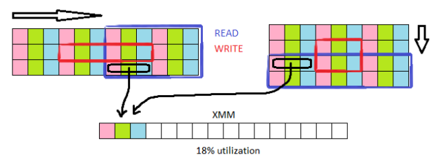
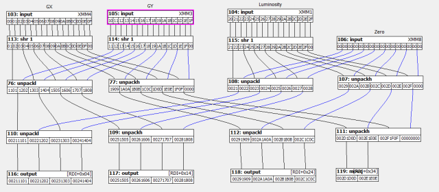
To make it from uchar[16] XMM registers we need to use the PUNPCK[L/H][BW/WD] instructions. I hate these instructions because I always mismatch them, also with the 2 operand model I always need to save values too. But with the aid of my little visual tool it was easy to design.

pic4.png

The output component interleaver.

This output stage is also ensures that only the inner 14 pixels are written, given by the 3×3 convolution window that works on 16 sse bytes.

//in: XMM4:GX, XMM3:GY, XMM14:Luma, XMM8:0
//out: RDI+0x4..RDI+0x3C, 14 DWords
psrldq XMM4,1;  psrldq XMM3,1;  
movaps XMM5,XMM14; psrldq XMM5,1;  
movaps XMM6,XMM4;  punpcklbw XMM4,XMM3;
movaps XMM7,XMM6;  punpckhbw XMM6,XMM3;
movaps XMM0,XMM5;  punpcklbw XMM5,XMM8;
punpckhbw XMM0,XMM8;  movaps XMM10,XMM4;  punpcklwd XMM4,XMM5;
add RDI, RDX; 
punpckhwd XMM10,XMM5; movups [RDI+0x04],XMM4;
movaps XMM5,XMM6;     movups [RDI+0x14],XMM10;
punpcklwd XMM6,XMM0;  movups [RDI+0x24],XMM6;
punpckhwd XMM5,XMM0;  movq [RDI+0x34], XMM5;

The above code is not so human readable but it was generated from the preceding dataflow diagram.


pic6b.png

From left to right: Original;  GX;  GY;  (GX, GY); (0, 0, Luma);   (GX, GY, Luma)

Extending the algorithm to the whole image

A lot of work is needed to upgrade the optimized algorithm to be able to work on real life data. In my opinion this is the most boring part of optimization. Sometimes I mix the unpoptimized version with the optimized one. But this time it makes more sense to use the faster optimized version everywhere with a bit of redundancy at the edges.

There are 3 areas of an image that need to be processed by differently:

pic6.png

  • The 1 pixel border of the image which has insufficient data for the 3×3 convolution matrix. -> I choose to fill this with neutral 0x8080 values.
  • The center area (width-2)*(height-2) should be filled with the new 14×14 routine.
  • And finally there is a region on the right that is under 14 pixels of width and also on the bottom. The right side will be filled with a 14×14 routine. The bottom side will be filled with reduced height 14xN sse routines. (This will set the minimal input image size to 16×3).

For this I need a function which works on one horizontal ‘run’. I also introduce an ycount value, so the unique height of the last run can be specified:

void SSE_sobelRun(ubyte* src, uint* dst, size_t stride, size_t xcnt, size_t ycnt){ asm{
  mov R10, src; mov R11, dst; 
  mov RDX, stride; shl RDX, 2; //this is the dst stride which is 4x bigger because ubyte->uint

  pxor XMM8, XMM8; //const 0
  pcmpeqb XMM9, XMM9; //const -1

  mov R9, xcnt;
  l0:
    mov RAX, R10; mov RDI, R11;

    movaps XMM0,XMM1; movaps XMM1,XMM2; movups XMM3,[RAX]; add RAX, stride; movaps XMM13,XMM14; movaps XMM14,XMM15; movaps XMM15,XMM3; movaps XMM2,XMM3; movaps XMM4,XMM3; pslldq XMM2,1; psrldq XMM4,1; pavgb XMM2,XMM4; pavgb XMM2,XMM3; 
    movaps XMM0,XMM1; movaps XMM1,XMM2; movups XMM3,[RAX]; add RAX, stride; movaps XMM13,XMM14; movaps XMM14,XMM15; movaps XMM15,XMM3; movaps XMM2,XMM3; movaps XMM4,XMM3; pslldq XMM2,1; psrldq XMM4,1; pavgb XMM2,XMM4; pavgb XMM2,XMM3;

    mov R8, ycnt;
    l1:
      movaps XMM0,XMM1; movaps XMM1,XMM2; movups XMM3,[RAX]; add RAX, stride; movaps XMM13,XMM14; movaps XMM14,XMM15; movaps XMM15,XMM3; movaps XMM2,XMM3; movaps XMM4,XMM3; pslldq XMM2,1; psrldq XMM4,1; pavgb XMM2,XMM4; pavgb XMM2,XMM3; 
      //here we have 3 GY rows in XMM0..XMM1
      movaps XMM3,XMM2; movaps XMM4,XMM0; pxor XMM4, XMM9; pavgb XMM3,XMM4; //XMM3: GY

      movaps XMM4, XMM13; pavgb XMM4, XMM15; pavgb XMM4,XMM14; //XMM4: vertical convolution with [1,2,1]
      movaps XMM5, XMM4; pslldq XMM4,1; psrldq XMM5,1; //XMM4, XMM5: left/right neighbors
      pxor XMM4, XMM9; pavgb XMM4,XMM5; //XMM4: GX

      //pack RGBA(GX,GY,Luma,0)
      psrldq XMM4,1; psrldq XMM3,1; movaps XMM5,XMM14; psrldq XMM5,1; movaps XMM6,XMM4; punpcklbw XMM4,XMM3; movaps XMM7,XMM6; punpckhbw XMM6,XMM3; movaps XMM0,XMM5; punpcklbw XMM5,XMM8; punpckhbw XMM0,XMM8; movaps XMM10,XMM4; 
      punpcklwd XMM4,XMM5; add RDI, RDX; punpckhwd XMM10,XMM5; movups [RDI+0x04],XMM4; movaps XMM5,XMM6; movups [RDI+0x14],XMM10; punpcklwd XMM6,XMM0; movups [RDI+0x24],XMM6; punpckhwd XMM5,XMM0; movq [RDI+0x34], XMM5;

    dec R8; jnz l1;

    add R10, 14; add R11, 14*4; //advance next block to the right 
  dec R9; jnz l0;
}}

The above code can transform an area where height = ycnt+2; and width = 2+xcnt*14;
The following code will utilize this sse function to transform a arbitrary sized image. It also keeps the blockHeight at 14 pixels for better cache locality.

void SSE_sobel(Image!ubyte src, Image!uint dst, bool main){
  enum BW = 14,         //blockWidth 
       BH = BW,         //blockHeight
       def = 0x8080;    //default color

  dst.size = src.size;
  int w = src.width,  
      wBH = w*BH, 
      h = src.height;

  if(w<=BW+2 || h<3) { sobel(src, dst); return; } //revert to slow algo
               
  int xBlocks = (w-2)/BW,
      yBlocks = (h-2)/BH,
      xRemaining = w-2-xBlocks*BW,
      yRemaining = h-2-yBlocks*BH,
      xLastIdx = xRemaining ? w-16 : 0;
  
  dst.data[0..w] = def; //first default line

  void doRun(int y, int yCnt=BH){ 
    int ofs = y*wBH; 
    foreach(i; 1..yCnt+1) dst.data[ofs+i*w] = def; //left side
    SSE_sobelRun(&src.data[ofs], &dst.data[ofs], w, xBlocks, yCnt); //blocks
    if(xLastIdx) SSE_sobelRun(&src.data[ofs+xLastIdx], &dst.data[ofs+xLastIdx], w, 1, yCnt); //last block 
    ofs += w-1;  foreach(i; 1..yCnt+1) dst.data[ofs+i*w] = def; //right side
  }

  foreach(y; 0..yBlocks) doRun(y);
  if(yRemaining>0) doRun(yBlocks, yRemaining);

  dst.data[$-w..$] = def; //last default line 
}

And before the benchmark results, here is the original D sobel function:

void sobel(Image!ubyte iSrc, Image!uint iDst){ //input: 8bit luminance   Output:32bit (GX, GY, Luma, 0)
  iDst.size = iSrc.size;
  const w = iSrc.width,
        h = iSrc.height;

  auto src = iSrc.data;
  auto dst = iDst.data, dst2 = dst;
  enum def = 0x8080;
  if(w<3 || h<3){ dst[0..w*h] = def; return; } //too small

  int w2 = w*2;

  dst[0..w] = def; //clear first line
  dst = dst[w..$]; //go to next line

  foreach(int y; 1..h-1){
    int d0 = y*w;

    dst[0] = 0;//first pix
    foreach(int x; 0..w-2){
      int smp(int ofs){ return cast(int)src[ofs+x]; }
      int gx =( 1*smp(0   ) +2*smp(  w ) +1*smp(  w2)
               -1*smp(2   ) -2*smp(2+w ) -1*smp(2+w2) )>>3;
      int gy =( 1*smp(0   ) +2*smp(1   ) +1*smp(2   )
               -1*smp(0+w2) -2*smp(1+w2) -1*smp(2+w2) )>>3;

      uint i2u(int a){ return (a+128); }
      dst[x+1] =(i2u(gx)             )|
                (i2u(gy)          <<8)|
                (smp(w+1)        <<16);
    }
    dst[w-1] = def;//last pix

    dst = dst[w..$];  src = src[w..$]; //advance
  }

  dst[0..w] = def; //last line
}

Benchmark results

Test image size: 1600*1200
System: CPU: AMD FX-8350, 4.1GHz, Ram: 2133MHz Dual Ch, Win10 64bit
Compiler: LDC – the LLVM D compiler (1.6.0)
Compiler options: ldmd2 – m64 – mcpu=athlon64-sse3 -mattr=+sse3 -release -O -inline -boundscheck=off

Results: 10.2ms vs 2.5ms    That’s 4.1x speedup for the first test ever.

Let’s tune it up!

There are 2 things on my mind: cache handling and choosing the ideal blockheight.

Cache handling: From now I use the prefetcht0 instruction in the row_fetch code:

movaps XMM0,XMM1; movaps XMM1,XMM2; movups XMM3,[RAX]; add RAX, stride; 
movaps XMM13,XMM14; movaps XMM14,XMM15; prefetcht0 [RAX]; movaps XMM15,XMM3; 
movaps XMM2,XMM3; movaps XMM4,XMM3; pslldq XMM2,1; psrldq XMM4,1; 
pavgb XMM2,XMM4; pavgb XMM2,XMM3;

For the memory writing operations I’m unable to skip the cache because movntps needs to be aligned to 16bytes. Out algorithm can only guarantee 4 byte align.

Interestingly with the 1600 pixels wide image it turned out that blockHeigh=2 is the best height. This way the algorithm reads a 1600*(1+2+1) area and writes a 1600*2*4 area in one ‘run’. So I’ve upgraded the blockHeight calculation like this:

BH = (4096/src.width).clamp(2, BW)

Final results: 10.2ms vs 2.2ms    speedup: 4.6x

There are still some minor improvements in my mind but those aren’t worth the time. For example: Currentle the 2 input rows and the 3 [1,2,1] premultiplied rows are stored in a queue in XMM0..XMM2 and XMM14..XMM15. Some move instructions could be eliminated if those would be true circular buffers. But that would make the code 3x bigger and 10x nastier. Probably wouldn’t worth the effort.

Checking the code generated by LDC2

pic7.png

No signs of auto-vectorization here. The math is done by mainly LEA, SUB, SAR.

Conclusion

Although when I work with SSE byte[16] data I always expect 16x speedup, with this algorithm I only achieved 4.6x.  For the first try it’s ok.  I’d give 3 out of 5 stars…

Posted in SSE | Tagged , , , , , , , , | 2 Comments

Compiling speed of DLang compilers.

I wanted to see what is the best way to compile small dlang projects, so I made a benchmark for it.

Here are the things checked:

  • Compiler used: DMD or LDC
  • Release(with optimization) or debug
  • Target: win32 or win64
  • Build type: Incremental(all modules are compiled in parallel, then linking) or one step build it with the compiler.
  • module count: 4 vs 13(more opportunity to do it in parallel)

The system: AMD FX-8350 4.2GHz, 2.4GHz ram, SSD

And the results:

compiler_speed_test1.png

For only 4 modules the fastest is DMD single pass compilation but it without optimization. Single pass compilation for LDC is a bit slower, and it is much slower when optimization is turned on, but with incremental compilation it is only 1.5x slower than DMD_DBG. So I think the winner here is LDC.

compiler_speed_test2.png

For a larger number of moduiles(13) incremental compilation helps a lot for LDC, but not that much for DMD.

The incremental builds in these tests was used for compiling all the modules. In the next test I measured what’s the case when incremental compilation is only recompiling 1 modified module and it uses the precompiled object files for the other modules. This is more like a real life situation.

compiler_speed_test3.png

It takes only 3-4 seconds to launch the exe file and start testing it. In the C++ world it is usual to spend 20 seconds on compilation plus 5-10 seconds to launch a debugger this time is so long, sometimes I totally forget why I launched the exe in the first place lol. And also it is important to test optimized release code in an instant because I can have the same experience with it, like the users get.

There is an optimization opportunity when using the MS Linker (from VS2017). I currently use the msvcenv.bat file to setup the environment variables for the MS Linker. It would be better to cache those environment variables to get 0.5sec better times for all LDC builds and for the 64bit DMD builds too.

Posted in Uncategorized | Tagged | 2 Comments

My first impressions of 64 bit DLang compilers.

Recently I’ve decided to step out of my 32bit comfort zone and move to the x64 world which was introduced 15 years ago (Yes, I’m slow :D). I was worried about having to step into the Matrix and stuff, but the D community is really helpful, they gave me instant help even for my n00best questions.

I planned not only to try the official DMD compiler which is fast and implements all the goodies of D, but also the LDC compiler which has known by having strong optimization. I will test a simple vector expression and see how the compilers can optimize that. I’ll do a human-optimized version too, to be able to compare to something.

The test expression

a = a*b+c; 

Where a,b,c are arrays of 32bit floats. This is a bit “memory heavy” (2 float ops and 4 io ops), but will do for testing.

Various implementations

1. simple float ops in a loop. The classic way to do this.

foreach(i; 0..a.length) a[i] = a[i]*b[i]+c[i];

2. float[] vector ops. The most elegant form in D.

a[] = a[]*b[]+c[];

3. float4 ops in a loop. When you think you’re helping the compiler.

import core.simd;
auto a4 = cast(float4[])a, 
     b4 = cast(float4[])b, 
     c4 = cast(float4[])c;
foreach(i; 0..a4.length) 
  a4[i] = a4[i]*b4[i]+c4[i];

4. float4[] vector ops. Same, but let Dlang do the indexing.

a4[] = a4[]*b4[]+c4[];

5. float4 __simd() intrinsics. You can specify what exactly you want to do in SSE, while the compiler can still inline/unroll your code. At least I think so. Sadly, not implemented in LDC.

foreach(i; 0..a4.length) 
  a4[i] = __simd(XMM.ADDPS, __simd(XMM.MULPS, a4[i], b4[i]), c4[i]);

6. inline asm (no unroll). A lot of writing. Optimized by carbon based organic intelligence :D.

//R8=a, R9=b, R10=c, R11=count
mov RCX, 0
 L0: movaps XMM0, [R8 +RCX*4]; 
     mulps  XMM0, [R9 +RCX*4]; 
     addps  XMM0, [R10+RCX*4]; 
     movaps [R8 +RCX*4], XMM0; 
add RCX, 4; 
cmp RCX, R11; 
jb L0;

7. inline asm (4x unroll). 4x more to write. Interleaved to help the CPU looking ahead. Also 4x more opportunities for typing errors. This is the best I can do. (Loop handling omitted.)

movaps XMM0, [R8 +RCX*4+00];   
mulps  XMM0, [R9 +RCX*4+00];  movaps XMM1, [R8 +RCX*4+16]; 
addps  XMM0, [R10+RCX*4+00];  mulps  XMM1, [R9 +RCX*4+16];  movaps XMM2, [R8 +RCX*4+32];
movaps [R8 +RCX*4+00], XMM0;  addps  XMM1, [R10+RCX*4+16];  mulps  XMM2, [R9 +RCX*4+32];  movaps XMM3, [R8 +RCX*4+48]; 
                              movaps [R8 +RCX*4+16], XMM1;  addps  XMM2, [R10+RCX*4+32];  mulps  XMM3, [R9 +RCX*4+48];      
                                                            movaps [R8 +RCX*4+32], XMM2;  addps  XMM3, [R10+RCX*4+48];      
                                                                                          movaps [R8 +RCX*4+48], XMM3;

Test conditions

I’m using an AMD FX-8350 @4.1GHz, dual ch ram at 2.4GHz. Only 1 core loaded.
I’m using VisualD, compiling in RELEASE mode. I don’t know the exact command line, but I guess it will add all the necessary options to build the fastest executable.
Later I will change the array sizes to fit in different cache/ram levels. Starting with L1 cache range where most of the performance differences can show up.

The first test is DMD 64bit with 12KB memory footprint (fits well in L1).

dmdtest.png

Before analyzing this, here are the LDC 64bit 12KB results:

ldctest.png

So this is why they mention “strong optimization” at LDC and they doesn’t mention it at DMD. I’m totally amazed by LDC. Maybe the test expression is simple, but this means I will never have to think about manually optimizing simple things for SSE in the rest of my life.

After examining the LDC generated code: It exactly does my version of “inline asm (4x unrolled)” with a bit different way of interleaving the instruction stream, but it still driver the one data io port of my core at 100%. We can see that when not unrolling the loop, thus not making space for the MULPS instruction’s 3 cycle latency means 192->253 = 30% slowdown. The great thing is that LDC optimizes consequently, it doesn’t matter what language features I’m using. So I can use the most compact way, the D vector[] operations wherever I want.

This is the awesome 4x SSE unrolled loop, that LDC automatically generates, regardles off the high level form of the algorithm:

L0: movups xmm0, [r9+rcx*4] 
movups xmm1, [r9+rcx*4+0x10] 
movups xmm2, [r10+rcx*4] 
mulps xmm2, xmm0 
movups xmm0, [r10+rcx*4+0x10] 
mulps xmm0, xmm1 
movups xmm1, [r10+rcx*4+0x20] 
movups xmm3, [r10+rcx*4+0x30] 
movups xmm4, [rdx+rcx*4] 
addps xmm4, xmm2 
movups xmm2, [rdx+rcx*4+0x10] 
addps xmm2, xmm0 
movups [r10+rcx*4], xmm4 
movups [r10+rcx*4+0x10], xmm2 
movups xmm0, [r9+rcx*4+0x20] 
mulps xmm0, xmm1 
movups xmm1, [r9+rcx*4+0x30] 
mulps xmm1, xmm3 
movups xmm2, [rdx+rcx*4+0x20] 
addps xmm2, xmm0 
movups xmm0, [rdx+rcx*4+0x30] 
addps xmm0, xmm1 
movups [r10+rcx*4+0x20], xmm2 
movups [r10+rcx*4+0x30], xmm0 
add rcx, 0x10 
add rsi, 0x2 
jnz L0

Note that it loads every operand as they were unaligned. This could be a problem, but not at this example, because the bottleneck is IO, and there is always present a free execution unit that can handle the unnecessary load instructions.

The performance of DMD is not that good. But I will not forget about it because it has lightning fast compilation speeds, making development with instant feedback easy. (I’m coming from Delphi. Where 2-3 seconds of build-time is enough for 150K LOC. 0.2sec needed if you modify only a top level module. I know what it feels like 😉
So the worst case in DMD is when doing things traditionally by making a loop and indexing everything. There is no auto vectorization, it translates to simple single operand SSE instructions:

L0: mov rax, [rbp-0x18] 
cmp rax, [rbp-0x10] 
jae 0x7ff7f0c715fa 
mov rax, [rbp-0x18] 
mov [rbp-0x8], rax 
mov rax, [rbp-0x18] 
shl rax, 0x2 
mov rcx, [rbp+0x20] 
mov rcx, [rcx+0x8] 
lea rcx, [rax+rcx] 
movss xmm0, [rcx] 
mov rdx, [rbp+0x18] 
mov rdx, [rdx+0x8] 
movss xmm1, [rax+rdx] 
mulss xmm0, xmm1 
mov rdx, [rbp+0x10] 
mov rdx, [rdx+0x8] 
movss xmm1, [rax+rdx] 
addss xmm0, xmm1 
movss [rcx], xmm0 
inc qword [rbp-0x18]
jmp L0

Well this looks like the same size as the previous LDC code snippet, but it does only 1/4 of the job, and a lot else of what is not essential for the job.

It doesn’t use register optimization, holds everything, even the loop counter on the stack. In 64bit, it would have a lot (like 12) general registers at hand, but there are sufficient amount of them even on 32bit too for this purpose.
It reads the ptr-s of the slices every time from memory, and storing every slices as reference too, because they’re input parameters. (Now this is a difference between DMD and LDC: DMD passes slices as reference (according to Microsoft’s 64bit spec), and LDC is putting the whole 16byte slice struct on the stack.)
There is an optimization: It calculates i*sizeof(float) (What did I say?!!! float.sizeof, I mean :D) from the loop index, and it uses it 3 times. It does the SHL2 manually, although it would be specified with no cost in the intel SIB byte.
So basically this looks like DEBUG code, but I’m 100% sure, I choosed RELEASE DMD 😀

Let’s see DMD’s best optimization which fortunately generated for the most beautiful code format: the vector[] operations.

L0: mov rcx, r11       //r11 is the float[] index, rcx is the byte index
                       //we only need one of them in the loop
shl rcx, 0x2           //Can do with SIB
mov r8, [rbx+0x8] 
movups xmm0, [rcx+r8]  //unaligned reads, still an opportunity for manual opt
mov r9, [rax+0x8] 
movups xmm1, [rcx+r9] 
mulps xmm0, xmm1       //it does the actual vectorization, but not the 4x unroll
mov r10, [rdi+0x8] 
movups xmm2, [rcx+r10] 
addps xmm0, xmm2 
mov r8, [rsi+0x8] 
movups [rcx+r8], xmm0 
add r11, 0x4 
dec rdx 
test rdx, rdx          //dec just updated the zero flag already. Just sayin' :D
jnz 0x7ff7ce6b1ec8

So it did well, with a bit of additional math.

Tests including bigger memory footprints

I’ve also tested L2 size (1.5MB footprint), and on RAM size (48MB). Here are the results on a chart:

dmdldcchart.png

Nothing unusual there, the unoptimal things in the DMD SIMD variants are smoothed out as the memory footprint rises, because waiting for uncached memory became the bottleneck there.

And LDC’s performance is just amazing (just as me lol,… kidding :D). In a future post I will investigate what is the compile time cost generating such greatly optimized code…


Posted in SSE | Tagged , , , , | Leave a comment

Fast SSE 3×3 median filter for RGB24 images

Optimization opportunities:

After a bit of googling, a good solution to the problem would be a partial sorting network which only uses the median value.
[1] -> https://software.intel.com/sites/default/files/m/d/4/1/d/8/MedianFilter.pdf

Another way of optimization is to reuse intermediate data by doing not only one but more median kernels at a time.
[2] -> https://www.cg.tuwien.ac.at/research/publications/1994/Kopp-1994-EMF/TR-186-2-94-18Paper.pdf

The paper said that they reached 3x speedup by found 2 kernels at once, and reusing data while moving the kernel forward by 2 pixels.

Also SSE can really speed up this because it has 16x parallel min/max functions, I think the biggest speedup will come from this, so all the algorithm must be twisted in a way to support SSE as possible as could. This algo has a lot of computation and a moderate amount of memory IO, this is good for SSE.

Finally there’s multithreading, but it’s so straightforward, I don’t even will implement it.

Let’s plan the algorithm

First we need some basic sort network to start from. We need a 9 element sorting network for this. I choose the one that groups the data at the beginning into 3×3 element groups. There 3 element groups will represent the column of out moving 3×3 kernel window.

Here’s an online generator -> http://pages.ripco.net/~jgamble/nw.html
The variant called “Best” seems like to suit our needs well. -> http://jgamble.ripco.net/cgi-bin/nw.cgi?inputs=9&algorithm=best&output=svg

sortnet1.png

When visualizing data paths of the median value, it turned out that 5 min/max operations aren’t used at all and removing those we can reduce the operation count from 25 down to 20. This trick is used in the Intel Optimization paper [2].

After reorganizing a bit we can see the 3 element sort ranges at the beginning, these operations will be reused by adjacent kernels. Also there is a noticeable 6 element group. Also after making an error checker, it turned out that one additional operation can be eliminated.

sortnet2.png

Now let’s expand it to a 2 kernels, where we have 4 input columns, 12 values in total, and we need to pull 2 medians.

sortnet3.png

The workflow:

  • At every iteration, we move the 2 kernels forward by 2 pixels: copying 2×6 sorted values (light green) and sorting 2*3 incoming ones: 6 minmax ops 6 moves
  • Then the purple rectangle comes, this is a preparation step. 2 minmax ops
  • The next orange stage is to save 5 values for later use: 5 moves
  • And finally the two median calculations: 2*8 minmax ops, 5 moves (recovering saved orange values)

Total min/max ops: 6+2+2*8=24, total moves=5+5+6=16
That’s 12 minmax per one median value, it’s 60% more efficient than the single kernel partial sorting network.
There were attempts to optimize this further in 2D [1], but the gain was so small compared to the 1D version that I don’t want to make the algorithm bigger.

SSE estimation: In the worst case, a minmax op will use 3 cycle and a move will use 1. So the total cycle count is 12*3+8= 44 cycles for each median calculation. By using SIMD with byte data we’ll have 16 lanes, thus the cycle estimation is around 2.8 cycles for each median calculation. (not including fetch and store phases, those will be the biggest problem in this median filter because of 24bit input data, it will be discussed later.)

The two building blocks we need are these:

MinMax: Will use a temporary register and an sse min and max instruction. The result will be always in a register, one of the inputs can come from a memory location. There will many combinations of inputs used (reg/mem), also in contrast to the non-partial sorting networks here we gonna have unused outputs of either the min or the max functions. I will not try to code these manually, I will use an automatic instruction flow generator tool for this, that will handle register automation too, I only have to watch out for the proper instruction order.

Move: It will be implicit as I’m using the Instruction flow generator thingie.

Fetch and Store

This will be quite32 difficult because of the nature of RGB24.
First have to decide in which direction we want to process the data in the 2D bitmap.

sortnet4.png

There are two variations(for the above scalar example):

  • Left to right: This is the natural order of the system memory, so it would be so good for the cache.
  • Top to bottom: This is not so good for cache, would require additional prefetching, but at certain bitmap with it could still be able make cache useless.

Let’s widen it in order to fulfill an XMM register:

sortnet5.png

Now the register utilization is much better.
From the two variants I immediately throw de [left to right] on because it needs so many little reads, and that means a lot of shuffling in order to fill the register.
With the top down variant we could be able to read the memory in large chunks, and no complex shuffling is needed, the already loaded data can be reused by shifting. Additionally on recent systems that have the SSSE3 extension it would be even more effective by using this ‘super weapon’ called PALIGNR and even more complex shuffling can be achieved with the PSHUFB byte-permute instruction. But first, I’ll do it only with simple memory reads, and simple SSE instructions.

By thinking a bit more about the problem, that 93% register utilization can be simply extended to 100% because the only important thing in the current problem is not to separate RGB triplets properly, but only to pair the color components with their left neighbors. They are exactly 3 pixels away when using RGB, 4 pixels away when using RGBA and 1 pixels away with GrayScale. In other words it’s irrelevant if we group the colors like RGB, RGB, RGB, RGB or RGBR, GBRG, BRGB.

One last thing remains to deal with is the unnatural pattern of memory access. I’m thinking about 2 ways to solve it:

  • It’s easy to do but can’t solve cache conflicts.
  • Moving our window down like 10 times, then go up and right and do another run downwards adjacent to the previous run. This may help a lot with very large bitmaps. And still can be combined with prefetching by no cost.

When I implemented the algo, it turned out that we need both of the above. Prefetch is needed because the non-normal access pattern, and partitioning is needed to be able to stay inside the L3 cache.

Implementation details

It wasn’t so hard to implement this, I used the plan, rotated it by 90 degrees and designed it in my sse programming tool. Only 4 SSE instructions were used: MOVUPS for reads,  MOVAPS for stores and to move reg/reg data, and PMINUB/PMAXUB. On my FX-8350 cpu (AMD Piledriver architecture) it is possible to execute 2 MIN/MAX at one cycle, and those have only 2 cycle latencies, so this particular algorithm can run quite fast on it.

So here’s what the first design looked like:

median3x3_sse_plan.png

After some reordering and simplification it was possible to implement the whole algo on the 8 xmm registers and without any temp registers. But later I’ve noticed, that it’s not needed that much because I think the bottleneck is the rather L3 cache because of the unusual memory access pattern. Anyways, here’s what the cleaned up version looks like (note that, now the 16 SSE byte lane’s are visualized too):

median3x3_sse_plan2.png

The results:

lenna_median3x3.png

Personally I was amazed how fast it became.

The test config: AMD FX-8350 4.2GHz, 8MB cache, 2133MHz DDR3    Memory read speed=11.4 GByte/s
Tested with a big 3888*2592 RGB24 image (30Mbytes), the runtime on 1 core was only 9.84 ms, that is 2928 MByte/s image processing speed. Smaller images can run even faster because of better cache usage: I measured 3.4GByte/s on a small 640×480 image.
Compared to a non-SSE implementation written in a high level language, the difference was huge: An initial, lightly optimized, more readable version did it in 3.36 s (8.5MByte/s). This version can be found here: http://prog.hu/tarsalgo/?fid=194693&no=10#e10 Later on with various optimization (partial bubble-sort, faster data access) they were reached a 2x faster version. And finally with the introduction of FastDib/MMX routines (mixed with high level code) they got another 7.5x speedup on top of that 2x. Theoretically it’s 8.5*2*7.5=127.5MB/s. It’s theoretical, because I don’t have the sources to test those, I only rely on Stella_209’s time measurements on the forums. But it’s still so far away from this SSE version’s 2900MB/s. This shows the power of low level optimization because one well written inner loop can be much better that small highly optimized routines stitched together with other fast routines in a high level language. With rewriting the loop from scratch we can avoid unnecessary data movement and conversion, in addition to function call overheads, and most importantly we can twist the whole process around the SSE instructions that will do the heavy lifting in order to feed those instructions with the highest amount of data to work on.

Imperfections:

Yes, there are some but with a lot of work they can be fixed. This experiment was only to measure that how fast an SSE median filter can be in general.

  • Every 16th column is filtered twice because the 16wide kernel works in place and reusing a previous kernel’s output. Solution -> work into a separate output buffer.
  • Boundary conditions. I’m ignoring them at all. There can be also a big untouched gap on the left and right sides because the kernel only outputs 16byte aligned data. Solution -> handle the border situations by a traditional algo.

Source code:

The source code is relatively small. The assembly parts are compacted because they were just pulled out automatically from my SSE design tool in an order I controlled.

Compiled and tested on Delphi XE3 win32.

procedure SSE_median3x3_RGB_x2(dst:pointer; linesize, count:integer);
asm
  push esi push edi push ebx push ebp

  mov ebp,linesize  //ebp: linesize   //must be 16 aligned
  mov ebx,count     //ebx: counterr
  mov ecx,dst       //ecx: dst

  //calc src addresses
  mov eax, ecx   sub eax, ebp   sub eax, 3   //src = dst-linesize-3
  lea edx, [eax+ebp]  //one line down

  //prepare 2*7*$10 bytes of temp buffers
  mov esi, esp   sub esi, 2*$70;   and esi,not $FFF    //align temps to a 4K page
  lea edi, [esi+$70]  //the other half of the temp buffers

  //fetch the first 2 rows to the temp buffer
  movups xmm0,[eax] movups xmm1,[eax+3] movups xmm2,[eax+6] movaps xmm3,xmm0 pminub xmm0,xmm1 pmaxub xmm3,xmm1 movups xmm1,[edx]
  movaps xmm4,xmm3 pminub xmm3,xmm2 movups xmm5,[edx+3] pmaxub xmm4,xmm2 movaps xmm2,xmm0 pminub xmm0,xmm3 pmaxub xmm2,xmm3
  movups xmm3,[edx+6] movaps xmm6,xmm1 pminub xmm1,xmm5 pmaxub xmm6,xmm5 movaps xmm5,xmm6 pminub xmm6,xmm3 pmaxub xmm5,xmm3
  movaps [esi],xmm0 movaps xmm3,xmm1 pminub xmm1,xmm6 movaps [esi+$10],xmm2 pmaxub xmm3,xmm6 movaps [esi+$20],xmm4
  movaps [esi+$30],xmm1 movaps [esi+$40],xmm3 movaps [esi+$50],xmm5

  xchg esi, edi         //swap the temp banks,
  lea eax, [eax+ebp*2]  //advance the source offsets
  lea edx, [edx+ebp*2]

  cmp ebx, 0;  jle @end
  @1:
    //inputs      : eax, edx  : image source row0, row1
    //temps       : esi, edi  : 2x 7*16bytes alternating buffers. Last elements are used as 2 temps.
    //output      : ecx       : 2x 16bytes of output (used as temp internally)
    //remarks     : edx = eax+linesize;  next iteration: swap(esi,edi); eax += linesize*2;
    //source plan : SSEDesign_1610_Median3x3
prefetch [eax+ebp*2]  prefetch [edx+ebp*2]  //2.2->2.9 GB/s
    movups xmm0,[eax] movups xmm1,[eax+3] movups xmm2,[eax+6] movaps xmm3,xmm0 pminub xmm0,xmm1 pmaxub xmm3,xmm1 movups xmm1,[edx]
    movaps xmm4,xmm3 pminub xmm3,xmm2 pmaxub xmm4,xmm2 movups xmm2,[edx+3] movaps xmm5,xmm0 pminub xmm0,xmm3 movups xmm6,[edx+6]
    pmaxub xmm5,xmm3 movaps xmm3,xmm1 pminub xmm1,xmm2 pmaxub xmm3,xmm2 movaps [esi],xmm0 movaps xmm2,xmm3 pminub xmm3,xmm6
    movaps [esi+$10],xmm5 pmaxub xmm2,xmm6 movaps [esi+$20],xmm4 movaps xmm6,xmm1 pminub xmm1,xmm3 pmaxub xmm6,xmm3
    movaps [esi+$30],xmm1 movaps xmm3,[edi+$20] movaps [esi+$40],xmm6 movaps xmm7,xmm2 pminub xmm2,xmm3 movaps [edi+$60],xmm2
    movaps [esi+$50],xmm7 movaps xmm7,[edi+$10] movaps xmm3,xmm6 pminub xmm6,xmm7 pmaxub xmm3,xmm7 movaps [esi+$60],xmm6
    pminub xmm4,xmm2 pmaxub xmm5,xmm6 movaps xmm6,[edi] pminub xmm5,xmm3 pmaxub xmm0,xmm1 pmaxub xmm0,xmm6 movaps xmm2,xmm4
lea eax, [eax+ebp*2]  //advance the source offsets
    pminub xmm4,xmm0 pmaxub xmm2,xmm0 pmaxub xmm4,xmm5 movaps xmm5,[edi+$50] movaps xmm0,[esi+$60] pminub xmm4,xmm2
lea edx, [edx+ebp*2]
    movaps xmm2,[edi+$40] movaps [ecx+ebp],xmm4 pmaxub xmm2,xmm0 movaps xmm0,[edi+$60] pminub xmm5,xmm0 pminub xmm2,xmm3
    movaps xmm3,[edi+$30] pmaxub xmm3,xmm1 pmaxub xmm3,xmm6 movaps xmm6,xmm5 pminub xmm5,xmm3 pmaxub xmm6,xmm3 pmaxub xmm5,xmm2
xchg esi, edi         //swap the temp banks,
    pminub xmm5,xmm6 movaps [ecx],xmm5
lea ecx, [ecx+ebp*2]  //advance the dst offset too

    dec ebx jg @1
  @end:
  pop ebp pop ebx pop edi pop esi
end;

procedure applyMedian3x3(b:TBitmap);


  procedure Error(s:string);begin raise exception.Create('applyMedian3x3: '+s); end;
  function AlignUp(i:integer;const align:integer):integer; asm sub edx,1;  add eax,edx;  not edx;  and eax,edx end;

var base,dst0, ycnt, xcnt, w, h, x, y, yblocksize, ysiz, st, en:integer;

const L3CacheLimit=4096 shl 10;
begin
  if b.PixelFormat<>pf24bit then error('24bit format expected');
  h:=b.Height;  w:=b.Width*3;  if (w and 15)<>0 then error('Scanline size must be a multiple of 16');
  base:=integer(b.ScanLine[h-1]);

  //calculate first aligned dstByte (on the 0th line first)
  dst0:=AlignUp(base+w+3, 16);  //center of 3x3 window
  xcnt:=((base+w*2-3)-dst0)div 16;
  ycnt:=h shr 1-1;

  yblocksize:=ycnt;
  while(yblocksize>4)and(yblocksize*w*2>L3CacheLimit) do yblocksize:=yblocksize shr 1;

  while ycnt>0 do begin
    ysiz:=min(ycnt, yblocksize);
    for x:=0 to xcnt-1 do begin
      SSE_median3x3_RGB_x2(pointer(dst0+x shl 4), w, ysiz);
    end;
    ycnt:=ycnt-ysiz;
    inc(dst0, ysiz*w*2);
  end;
end;


Posted in SSE | Tagged , , , , | Leave a comment

GCN Quick Reference Card

Happy new year!

Most importantly here’s the document: GCN Reference Card

(Use it only on your own risk, as it can contain errors. The red color means the glorious GCN3)

Last autumn I had the opportunity to program a GCN3 Fury card. It is a real 8TFlops/s beast, even games are flowing incredibly on that while I still have a potato of a CPU 😀

So I had a job on it, and in order to do it, first I had to upgrade my assebler to support the changes that GCN3 introduced. I’ve spent the first days on comparing the old (Southert/Sea Islands) manual against the new one (GCN3 Isa Manual), spotting the differences, making notes on every important changes. The new instruction set is totally incompatible with the old one, but maybe first I was a bit angry, later I really liked the new changes. Just 2 things out of the many: Sub DWord Addressing, Data Parallel Processing. These two (mostly the latter) are kinda redefining how I think in parallel programming from now. Basically there’s no need to think in mass parallel, we can interweave adjacent threads without any wasted cycles(* there are penalties, though) to collaborate on the same job, while using the same memory resources as it would do with only 1 individual thread.

Long ago I thought about optimizing Scrypt on 4 adjacent lanes. I just guessed it is useful as it uses 1/4 the memory costs. On GCN1 it had to be implemented with the ds_swizzle instruction, but now it is free on the GCN3 to connect 4 lanes this way. Too bad I don’t have time to play with this…

5 years ago there was a mass parallel revolution (I’d call it hype), when sequential programmers were so optimistic to wait for new solutions that can make their sequential programs run on massive amounts of treads automatically. Now there is that inter-thread data sharing thing. If memory is a bottleneck, then we can think about connecting 2,4,16 or even 32 threads to work together on the same job. By this, it became even harder to optimize classic sequential code automatically to new hardware. But those guys are still optimistic as hell. I heard about someone who willing to wait these parallel things to be implemented under Java. Geeeeez 😀 Why not start OCL today?!

Posted in Uncategorized | Tagged | 1 Comment

Bitmap clock

Just got bored a bit and I’ve made a clock out of 6 decade counters and 7segment encoders. I’m starting to realize, that how much simpler it is to program these simple things rather than design their hardware.

clock

Update: Here’s clock V2.0. It is built entirely out of synchronous master-slave T flip-flops with synch’d clear. This way the circuit is much simpler. (And at least I finally know, how it works. :D)

clock2

Posted in Uncategorized | Tagged , | 2 Comments

Bitmap Logic Simulator

This post is not about GPU, it’s about low level computing.

Long ago I wanted to make a simple simulator, which can simulate logic gates with the simplest rules.
Earlier I’ve found  WireWorld An amazing logic simulation with really simple rules. I never played with it, I found that extremely difficult, that everything is in motion in this simulation when it’s working. I wanted something, that simulates logic gates in a similar way that in TTL electronics so I came up with these simple rules:

bitmap logic simulation rules

There are only five 3×3 pixel combinations that the simulation recognizes as special features: The wire crossing and the NOT gate facing all four directions. The OR behavior can be achieved when wires are connected to each others. And 2 serially connected NOT gates act like a buffer gate.

The simulation is working well with signal feedbacks:

  • Two NOT gates connected circularly is a memory cell. At startup it will have a random 0 or 1 bit, but will never oscillate because the simulation is upgraded with some randomness when changing logic states (just like in the real world where you’ll never have two logic gates that switches in the exact same time).
  • Odd number of NOT gates in a circular chain: They make an oscillator. The more gates used, the slower is the frequency.

Here are some more circuit examples:

JK_flipflop

Master Slave JK flipflop and its compact form

ttl chips

Some 74xxx chips

Now it’s enough information about the rules of the simulation. If you’re interested, you can find the Simulator and its (Delphi XE) source in the [Download Area] up on the menu bar of this page. Current link is: BmpLogicSim150902.zip  Let me see what incredible machines you can build with it! 😀

Using these instructions: [How-to-Build-an-8-Bit-Computer] I’ve managed to build a working machine that can compute the first 12 Fibonacci numbers. Well, that’s a… something… Now I have a bit more understanding on how things work under the hood… Next time I want to make it a bigger computer in order to make the classic Tetris game on it. Also it needs the simulator to be optimized 10..50x faster, but there are a lot of room for improvements in it.

So here’s the small computer on 1024×1024 resolution. First you have to click on [RESET], ant then on [RUN]. It will stop whenever a 8bit overflow happens in while calculating the Fibonacci series.

8bit_cpu

(When you load it, be patient, it take a few seconds to load and preprocess this circuit into the simulator)

Here’s a small video on how it works. Sry for bad quality.

Posted in Uncategorized | Tagged , | 75 Comments

Instructions: Compiling and running the ASM Groestl kernel in sgminer 5.1

(You can find more information and benchmark results on this page: https://realhet.wordpress.com/gcn-asm-groestl-coin-kernel/ )

Compiling the kernel for a specific GPU

Requirements:

  • Windows 7 or up
  • Catalyst 14.6, 14.7, 14.9,  14.12  (those are confirmed to work)
  • AMD Radeon gfx with GCN chip (HD7xxx and up)
  • sgminer 5.1

Step 1: Download HetPas??????_Groestl.zip! The latest version can be found in the [Download Area] on the MenuHeader of this blog.

Step 2: Unpack it to a folder that has write access (UAC let it to write there).

Step 3: Turn off DEP for HetPas.exe. (If you don’t know what is this and HetPas.exe wont start -> google “Turn off DEP”)

Step 4: Open HetPas.exe and load [F3] the “groestl/groestl_isa.hpas” program.

Step 5: Run the program by pressing [F9]! If everything goes well, you should see something like this:
groestl compile screen

Step 6: Run “sgminer.exe -k groestlcoin (…your usual command-line comes here)” and then stop it in order to precompile the original groestlcoin.cl opencl kernel.

Step 7: Look for the precompiled binary file that just have been created in the same path as sgminer.exe. The name of the file is something like this: “groestlcoinXXXXgw256l4.bin“. To the place of XXXX your graphics chip’s name will go. In my case it is “groestlcoinCapeverdegw256l4.bin”.

Step 8: Replace the binary file next to sgminer.exe with the “kernel_dump\kernel.elf” one you’ve created in Step 5.
groestl replace kernel

Step 9: Run sgminer.exe but now with the new binary!

Posted in Uncategorized | Tagged , , , , | 11 Comments

Testing the GCN ASM Groestl kernel using sgminer 5.1

Making the original and the new kernel identical (from the outside)

In the previous blog post I was at the point, that the desired kernel parameters (char *block, uint *output, ulong target) are worked well in a small test kernel. After it is applied to the main kernel only one thing left to realize in asm: Detecting if the result<=target and marking it in the output buffer.

  //compare and report result
  v_if_u64(g[0]<=target)
    enter \ v_temp addr, data, tmp \ s_temp oldE[2] align:2
    v_mov_b32     addr, $FF
    v_mov_b32     data, 1
    buffer_atomic_add  data, addr, resOutput, 0 idxen glc
    s_waitcnt     vmcnt(0)
    v_min_u32     addr, $FE, data //dont let it overflow

    //reverse byte order of gid
    v_bfe_u32 data, gid, 24, 8
    v_bfe_u32 tmp , gid, 16, 8 \ v_lshlrev_b32 tmp,  8, tmp \ v_or_b32 data, data, tmp
    v_bfe_u32 tmp , gid,  8, 8 \ v_lshlrev_b32 tmp, 16, tmp \ v_or_b32 data, data, tmp
                                 v_lshlrev_b32 tmp, 24, gid \ v_or_b32 data, data, tmp

    tbuffer_store_format_x  data, addr, resOutput, 0 idxen format:[BUF_DATA_FORMAT_32, BUF_NUM_FORMAT_FLOAT]
    dd $BF8C0F00 //s_waitcnt     vmcnt(0) & expcnt(0)
    leave
  _endif

Simple if/relation handling: v_if_u64() is not a GCN instruction. It is some kind of a macro that can identify the relation operation and does the appropriate compare instruction. It also jumps conditionally and saves/modifies the exec mask based on the compare result.

Atomics: Using atomic increase when calculating the next output index. In the original opencl I had to use atomic_inc(&output[0xFF]) as well because I’m using a special test which returns more than 100 values in the output buffer and got to make sure that no values are lost because of the concurrent incrementations of the output index.

Swapping byte order: Well that’s not too nice, I should rather find  some packing instructions, but this is not the inner loop, so I just don’t care… As thinking it a bit further: It would be pretty fast with this way: Swapping low and high words with v_bytealign. Selecting odd bytes with v_and, shifting them right 8bits. Selecting even bytes and scaling it up 256x and adding to previous result with v_mad_u32_u24. Only 4 simple instructions instead of 9. It’s fun how a functionality can be built from various ‘LEGO’ pieces of the instruction set.

New method of functional testing

Now the key is to compare the asm kernel to the original kernel. Here are the testing parameters:

  • Block: is the same randomly generated 80 bytes as before.
  • target: 0x0008FFFFFFFFFFFF  (must be high enough to generate more than 100 values in the output array)
  • global_work_offset: 567    (is quiet random too)
  • global_work_count: 256*10  *512   (approx. 1.2million)
  • compressing the output[]: Iterate through all the output values and multiply them with a large prime number (402785417) and summarize them together. Because the order of values are not important, only that counts that all the values must be in the array.
  • Checking whether 2 kernels are identical: Is the same as checking the compressed ‘hashes’ of the outputs.

Just for the record, the compressed output hash value calculated from the result of the above parameters is: 335485889931504896.

It was checked for both kernels and it was proven that the original and the new kernel calculates the *same results.
*Actually it is “pretty much the same” by checking the outcome of 1.2 million groestlCoin calculations using a relatively high target value.

Testing it live

Testing it by running sgminer 5.1 and replacing the precompiled kernel binary (groestlcoinCapeverdegw256l4.bin) with my new binary produced the expected 3.5x speedup. And I was kinda lucky because I got the first ‘accepthed’ after 10 minutes. The next one came 3 hours later. So I’m now more than sure that it works correctly. But of course we can only 100% sure when it earns 3.5x more coins than the OpenCL version. That thing I cannot test because I don’t have a mining rig.

my_first_grs

second_grs

Note that GPU1 did the mining, not GPU0. GPU1 is a HD7770 running 1000MHz (stock), and it has 640 streams, peak performance is 1.28 TFlops/s. It ran around 63 Celsius degrees. It’s kinda cool because bottleneck is LDS and L1.

In the next post I’ll write down the instructions on how to build a kernel on a specific GCN GPU and use it with SG 5.1.

Posted in Uncategorized | Tagged , , , , | Leave a comment

Making the GCN ASM Groestl kernel to run inside sgminer 5.1

There are basically two ways to do this:

  • Make the kernel binary 100% compatible with the original kernel
  • Apply modifications in sgminer to handle a my custom binary.

For the first option I have to mimic the kernel parameters of the original kernel. The following is a small dummy kernel that uses the same parameters:

__kernel void search(__global unsigned char* block, volatile __global uint* output, const ulong target) {
  if(target>0)
    output[get_local_id(0)] = block[get_global_id(0)];
}

The simple program in it ensures that none of paramerers are optimized out byte the OCL compiler. Let’s see how it looks like in asm (cat14.9):

  s_buffer_load_dword s0, s[4:7], 0x18        //domain gid base
  s_lshl_b32 s1, s12, 8                       //s1:groupid*256
  s_buffer_load_dword s4, s[8:11], 0x00       //s4: block ofs
  s_buffer_load_dword s5, s[8:11], 0x04       //s5: output ofs
  s_buffer_load_dwordx2 s[6:7], s[8:11], 0x08 //s[6:7] target
  s_waitcnt lgkmcnt(0)
  s_add_u32 s0, s1, s0                        //s0: domain base id
  v_lshl_b64 v[1:2], 0, 0                     //fill with zero
  v_cmp_ne_i64 vcc, s[6:7], v[1:2]            //target>0?
  s_cbranch_vccz label_0018
  s_add_u32 s0, s0, s4                        //s0: threadgroup base id + block ofs
  s_load_dwordx4 s[8:11], s[2:3], 0x60        //s[8..11]: block res
  v_add_i32 v1, vcc, s0, v0                   //v1:gid+block ofs
  s_waitcnt lgkmcnt(0)
  buffer_load_ubyte v1, v1, s[8:11], 0 offen  //block[gid]
  s_load_dwordx4 s[0:3], s[2:3], 0x68         //s[0..3]: output res
  v_lshlrev_b32 v0, 2, v0                     //v0:lid*4
  v_add_i32 v0, vcc, s5, v0                   //v0:lid*4+output base
  s_waitcnt vmcnt(0) & lgkmcnt(0)
  tbuffer_store_format_x v1, v0, s[0:3], 0 offen format:[BUF_DATA_FORMAT_32,BUF_NUM_FORMAT_FLOAT] //output[lid]
  s_waitcnt vmcnt(0) & expcnt(0)
label_0018:
  s_endpgm

Well this is pretty much code for doing a little more than nothing.
We can access the target int64 parameter indirectly form buffer s[8:11], it is loaded into s[6:7].
get_local_id(0) is in v0.
threadgroupId is in s1.
There are 3 resources provided to the kernel by the driver:
s[4:7] contains kernel domain parameters. The only thing used in this is the lowest index value of the 1D kernel domain rangle.
s[8:11] is a table full of base pointers (and sizes?) for the parameter buffers. It also contains value parameters.
s[2:3] this is actually a 64bit pointer that points to the table the of resources of out 2 buffer parameters.
So these things are provided at start. Following is the list of things that must be calculated:
get_global_id(0) is calculated as threadGroupId*256+get_local_id(0)+domain_base_id
BlockResource is loaded from s[2:3] along with BlockBaseOffset from s[8:11]
The same from OutputResource and OutputBase.

And now it is possible to access the parameters ‘block’ and ‘output’. IMO it is a bit messy, and the real problem is not even the mess: It’s the possibility to change all these input registers and functionality in future versions of the GPU drivers.

One additional buffer is not considered yet: In the groestlcoin.cl kernel there are some big constant arrays. The OpenCL environment pass these constant in a buffer silently. I just don’t know how is this works in the binary .ELF format. I can only put the data into the code stream and with the s_getpc_b64 instruction I can calculate the address of it and read it from there. But here comes an additional problem with the alignment of that data.

And finally as if it is not complicated enough: I’d have to modify my binary generator to be able to work with not only buffer parameters but from now with ordinal/float parameters as well.

Altogether I think this is the better way and not to make modifications in sgminer.

ver04: Packing the T tables into the code

As the orriginal kernel passes T0 and T1 in a silent buffer to the kernel, I have to do it in asm with a workaround.
First I generated a groestl_table.inc file with 16KB of constant declarations in asm style:

//contents of groestl_table.inc file
dd $A5F432C6
dd $C6A597F4
dd $84976FF8
...           //T0..T7: 16KB of data
dd $6D6DD6DA
dd $4E3A4E62
dd $2C2C3A58

Next step is to include this into the code:

  s_getpc_b64 s[40:41]  
  s_branch @tableEnd
  aligncode 16         //aligns the next code to the next 16 byte boundary 
@tableBegin:
  #include groestl_table.inc
@tableEnd:
  alias constBuf = s[40:43]  //make constbuf resource
  s_sub_u32 s40, s40, 4           \ s_subb_u32 s41, s41, 0 //beginning of code
  s_add_u32 s40, s40, @tableBegin \ s_addc_u32 s41, s41, 0 //physical offset of the table 
  s_or_b32  s41, s41, $00080000   //8byte record size
  s_mov_b32 s42, $FFFFFF00
  s_mov_b32 s43, $002A7204 

The above code first saves the value of the program counter, then includes the table data, and finally builds a 128bit resource constant in s[40:43] which points to the beginning of the table. Later in the program, this resource constant (called ‘constBuf’) will used for the lookups. Just a note to self, that it would be useful to be able to use @address labels in arithmetic expressions too (eg. @tableBegin-4).
The total code size is now 42KB, but the actual code which must fit into the ICache is 16KB less, only 26KB. The execution time of the new code remained the same as before.

Emulating the original kernel parameters

New things to be implemented in the compiler and on the host side:

1. There must be a way to specify the kernel header manually. The current system only works on buffers now (constant and uav buffers, although there is no difference between the two on GCN). So there is a second optional parameter for the TClDevice.NewKernel() function: oclSkeleton.

var isacode:=asm_isa(
  isa79xx
  numthreadpergroup 256
  numsgprs 48
  numvgprs 128
...
  s_engpgm
);

var skeleton:=
  "void main(__global unsigned char* block, volatile __global uint* output, const ulong target)
   { 
     if(target>0) output[get_local_id(0)] = block[get_global_id(0)]; //must use all parameters here
   }";

var var isakernel := dev.newKernel(isacode, skeleton); //<- optional skeleton opencl code

If the skeleton parameter is specified, then the base kernel will be generated by that code instead of an automatic skeleton code based on the oclBuffers instruction. In this the example the skeleton code specifies the same parameters as those used in the groestlcoin.cl kernel.

2. Also I have to enable to pass values (not just buffers) to the kernel in the host program. From now this can be realized using TClKernel.SetArg() calls:

isakernel.SetArg(0, block);
isakernel.SetArg(1, output);
isakernel.SetArg(2, int64(1234)); //must cast to int64 because otherwise it would be a simple 32bit integer.

3. Letting the kernel domain’s low range to be nonzero (global_work_offset). As I have seen sgminer is actively using this. So from now there is a new TClKernel.RunRange(offset, size, buf0, buf1, …) function.

isakernel.runRange(39,85).waitfor(); //that means run 85 workitems starting from gid=39. Also wait for it.

Testing dummy code with original kernel parameters

Here’s the assembly dummy code that does the same operation at it’s skeleton code:

#include stdgcn.inc

var i,j,k,dev:=findGCNDevice;   //or find the first GCN device.
writeln(dev.dump);

var isacode:=asm_isa(
  isa79xx
  numthreadpergroup 256
  numvgprs 128
  numsgprs 48
  ldssize 16384

  s_lshl_b32            s1, s12, 8                //groupid*256
  s_buffer_load_dword   s0      , s[4: 7], 0x18   //global_work_offset
  s_buffer_load_dword   s4      , s[8:11], 0x00   //block ofs
  s_buffer_load_dword   s5      , s[8:11], 0x04   //output ofs
  s_buffer_load_dwordx2 s[ 6: 7], s[8:11], 0x08   //target
  s_load_dwordx4        s[12:15], s[2: 3], 0x60   //block res
  s_load_dwordx4        s[16:19], s[2: 3], 0x68   //output res
  s_waitcnt     lgkmcnt(0)
  s_add_u32     s0, s1, s0                        //workgroup gid base
  s_add_u32     s12, s12, s4 \ s_addc_u32 s13 ,s13, 0  //adjust block res with offset
  s_add_u32     s16, s16, s5 \ s_addc_u32 s17 ,s17, 0  //adjust output res with offset
  v_add_i32     v1, vcc, s0, v0                   //gid
  alias lid = v0, gid = v1, resBlock = s[12:15], resOutput = s[16:19], target = s[6:7]

  v_temp_range 2..127
  s_temp_range 0..5, 8..11, 20..47

  v_temp zero[2], data, addr
  
  v_lshl_b64    zero[0], 0, 0                      //fill with zero
  v_cmp_gt_i64  vcc, target, zero[0]               //target>0?
  s_if(vccnz)
    buffer_load_ubyte  data, gid, resBlock, 0 offen  //block[g]
    v_lshlrev_b32  addr, 2, lid                      //v0:lid*4
    s_waitcnt vmcnt(0)
    tbuffer_store_format_x  data, addr, resOutput, 0 offen format:[BUF_DATA_FORMAT_32,BUF_NUM_FORMAT_FLOAT]
  _endif
  s_endpgm
);

var skeleton:="void main(__global unsigned char* block, volatile __global uint* output, const ulong target)
               { if(target>0) output[get_local_id(0)] = block[get_global_id(0)]; }";

var isakernel := dev.newKernel(isacode, skeleton);
isakernel.dump("dummyIsa\");

var block:=dev.newBuffer('rw', 512);
for i:=0 to 127 do block.Ints[i]:=i;

var output:=dev.newBuffer('rw', 256*4);
output.clear;

with isakernel do begin
  SetArg(0, block);
  SetArg(1, output);
  SetArg(2, int64(1));
  runRange(52,256).waitfor();

  for i:=0 to 255 do writeln(i, ' ', output.Ints[i]);
end;

As I’m using variable names in asm it’s not that messy as the raw disassembled version. Next time I’ll have to combine this with the groestl miner asm code and build the new binary. After that I gonna modify the functional test to make 100% sure, that not only the groestl calculations but also the thread-indexing is working correctly. With the new testing method, I’ll start at a nonzero global_offset and will use a relatively high target value to get around 100 hits. If I put it inside an iteration and give it randomized blocks and work_offsets, I’ll prove that the new kernel works exactly like the original one.

Posted in Uncategorized | Leave a comment